


I am a passionate, creative and self-learning engineer with a keen interest in technologies that enable a greener and more sustainable future. My academic experience encompasses numerical analysis, power converter control development and HIL testing, modeling and simulation and machine learning.

I received both my bachelor and master of science degrees from Instituto Politécnico Nacional and I had a semester-long stay at Silesian University of Technology in Poland as part of an international academic exchange program. During my studies I received various awards and distinctions, one of which being third place in the Instituto Politécnico Nacional contest for the best thesis at the bachelor level.
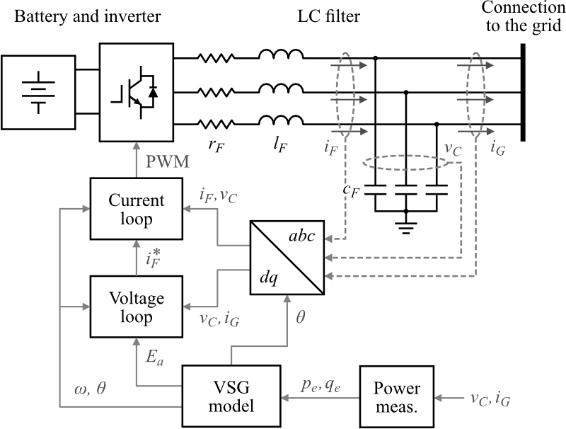
As part of my master thesis, I implemented a VSG inverter controller in an i.MX RT1060 microcontroller. This inverter controller, as shown in the following figure, comprises two inner cascaded voltage and current control-loops implemented on the synchronous reference frame and an outer Virtual Synchronous Generator model implementing the active and reactive power control. Furthermore, the VSG model of this controller features adaptive functionality provided by a reinforcement learning-trained agent aiming to optimize the performance of the virtual generator according to the grid's needs.
The control program for the inverter was developed in NXP's MCUxpresso IDE and written in C. The program runs on the FreeRTOS real-time operating system to ensure determinist response to events and employs single precision floating point arithmetic for all the calculations. Within this program, the low-level control-loops (voltage and current control) are executed through interrupt service rutines synchronized with the PWM pulse generation and the high-level control loops are executed as scheduled tasks inside the operating system. More information about this program may be found in source code hosted at this GitHub repository.
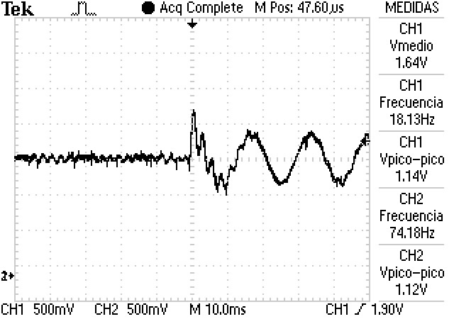
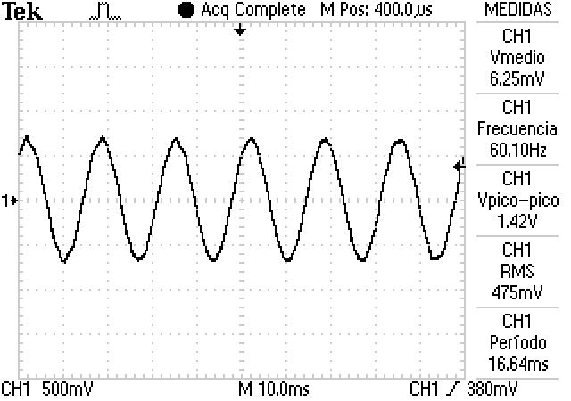
Once the control algorithm was implemented in the microcontroller, the inverter controller was tested by means of hardwdare-in-the-loop (HIL) simulation. For this purpose, an OPAL-RT real-time simulator was used to simulate an inverter connected to a stiff grid (fixed voltage and frequency) and generate the analog signals for the microcontroller, which in turn, sent the PWM pulses to control the inverter inside the simulation. Using this configuration, the cascaded voltage and current loops were tested with satisfactory results, as shown in the following oscilloscope screenshots.
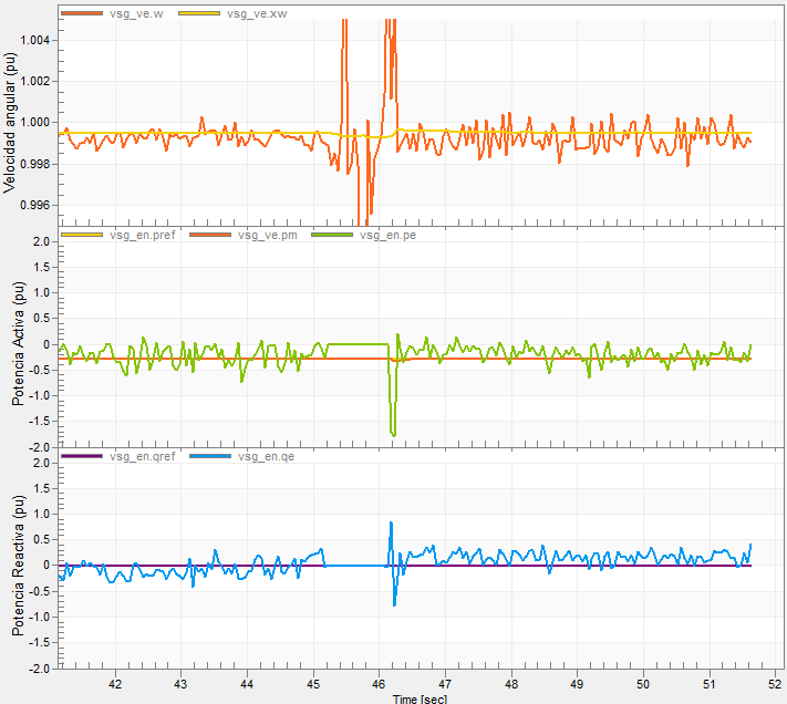
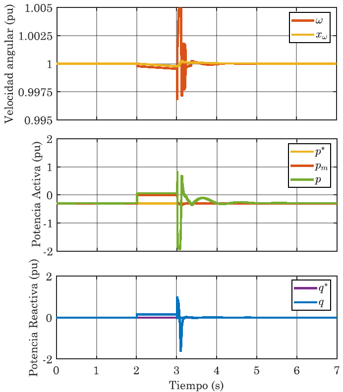
For a following test, the VSG inverter was subjected to a short circuit fault to verify the correct operation of the current protection scheme and to assess the ability of the controller to keep the virtual generator synchronized to the grid. The following two figures show that the VSG operated successfully in this test and remained synchronized with the grid, following the response seen in the simulations.
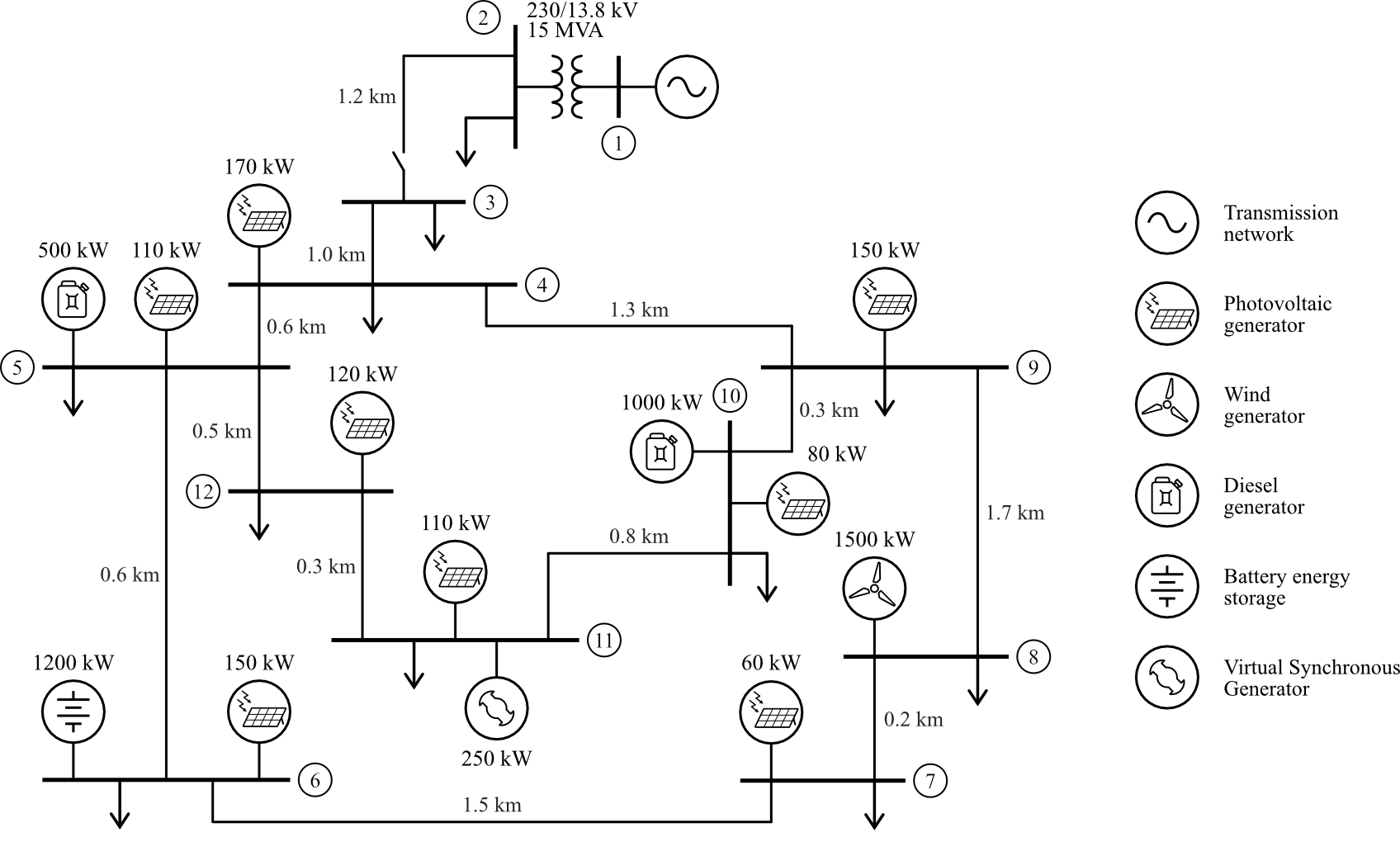
For this project I developed a time domail model of an AC microgrid that I used to train a reinforcement learning agent as part of my master thesis work. This microgrid model integrates multiple solar, wind and diesel generators, along with a Battery Energy Storage System and a Virtual Synchronous Generator (VSG) to feed several comercial and residential loads, operating either in grid-connected or islanded mode.
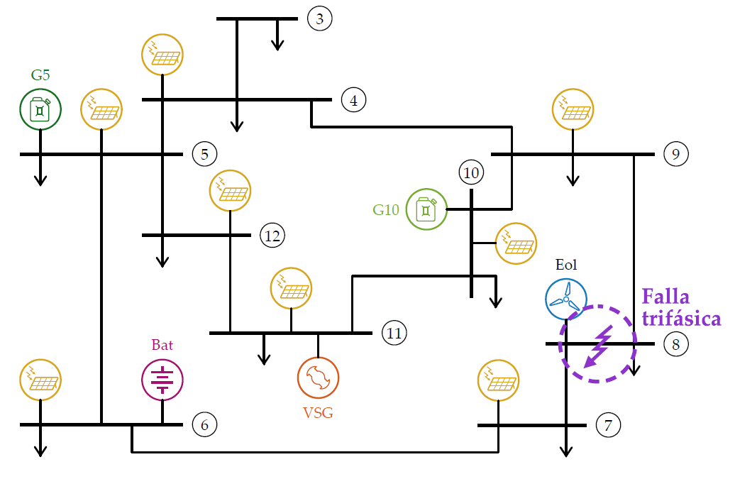
The follwing illustration shows a schematic diagram of the microgrid considered in this model, which is based on the medium-voltage distribution network benchmark proposed by CIGRE for Renewable and Distributed Energy integration studies.
The microgrid model was implemented in Simulink using custom blocks to model the different energy sources and loads such that the power output of the wind and solar generators follow a time series that represents the varying ambient conditions (solar irradiance, ambient temperature and wind speed) and the power consumed by the loads is adjusted according to residential and comercial load profiles.
Furhermore, to allow for the operation of the microgrid in grid-interconnected and islanded mode, the model also integrates a Microgrid Control Center that performs the following control functions:

Since the objective of this model was to serve as an interaction environment for the training a reinforcement learning agent implemented in Python, the model also integrates a Matlab-Python interface that allows the agent to interact with the simulation and retrieve all the information it needs to learn from this environment. In my master thesis I successfully used this model to train an intelligent adaptive controller for a Virtual Synchronous Generator.
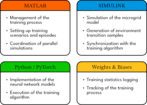
For my master's thesis, I developed a reinforcement learning-based intelligent controller for a Virtual Synchronous Generator (VSG) that dynamically adjusts the VSG's model parameters to optimize its power response, avoid the loss of synchronism and manage the energy storage. To achieve this, I developed a reinforcement learning platform that made it possible to train multiple agents simultaneously by running parallel simulations in Matlab and Simulink and implementing the learning algorithm in Python using Pytorch.
Employing this platform, the reinforcement learning agents were trained through simulation episodes where the agent controlled a VSG connected to a weak microgrid. In each episode, the microgrid was subjected to a disturbance such as a short circuit fault, a sudden transition to island mode, the loss of a generator, or a load change, and the agent was rewarded or penalized according to its performance adjusting the VSG's parameters. To train the agents, the TD3 actor-critic policy-gradient reinforcement learning algorithm was implemented.
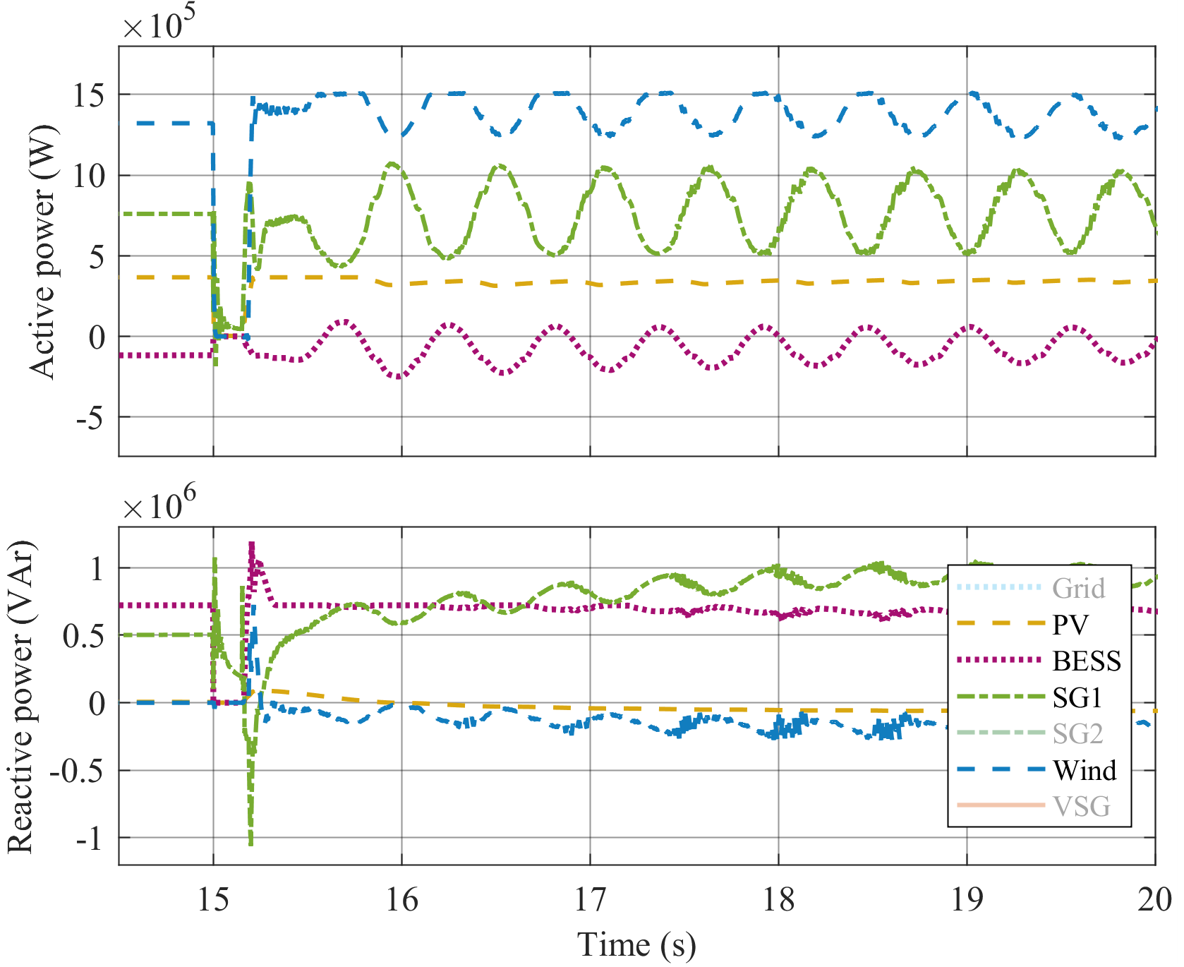
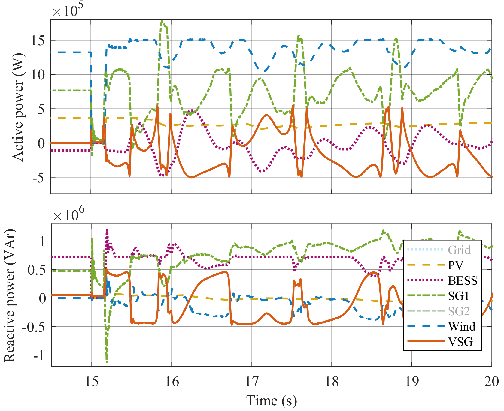
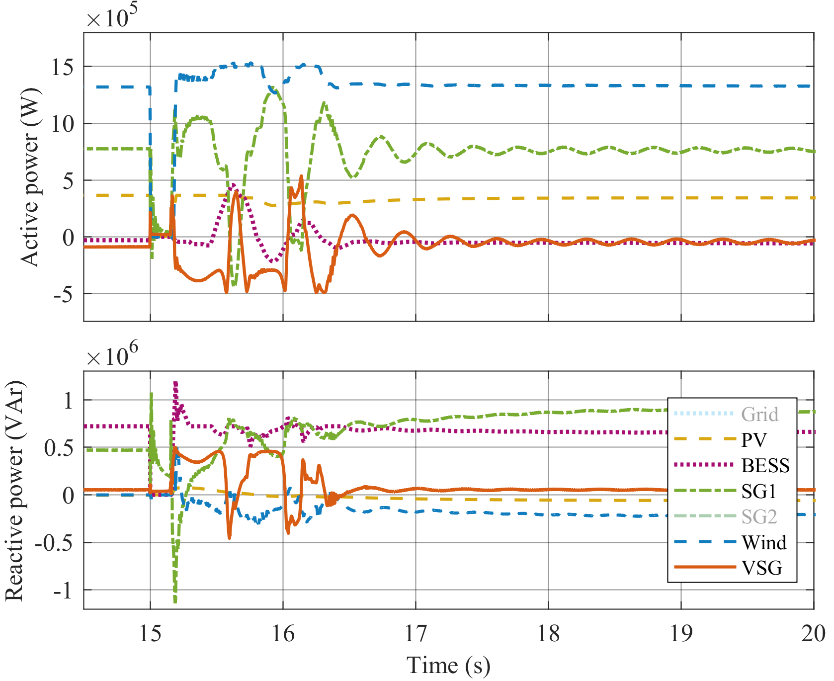
To showcase the performance of the final trained agent, a comparative simulation of a microgrid subjected to a 10-cycle symmetrical fault is shown next. In this simulation, three scenarios were considered: first the grid with no VSG, second the grid with a conventional VSG, and third the grid with the adaptive VSG (with the trained controller). In this case, it is clear that the intelligent controller prevents the loss of synchronism and contributes to damping the power oscillations in the microgrid, keeping it stable.
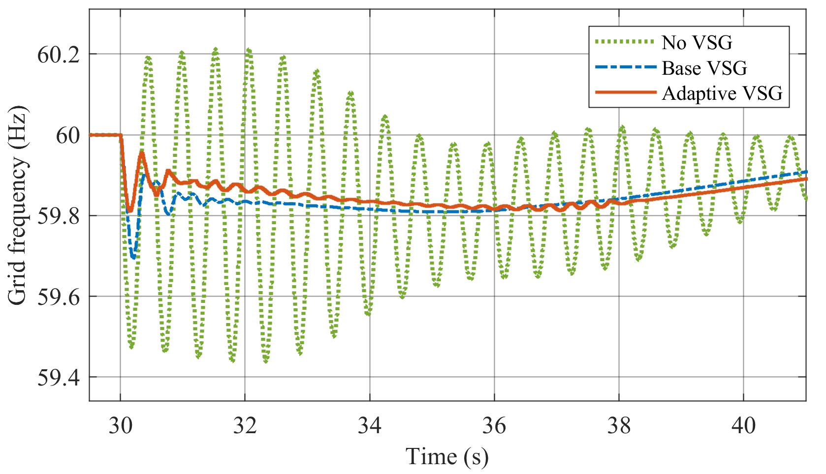
The following illustration shows the results of another such comparative simulation where the microgrid was subjected to a sudden islanding transition. In this case, it can be seen that both the regular and the adaptive VSG contribute to damping the oscillations and reducing the frequency drop in the microgrid, but thanks to the intelligent controller this improvement is further amplified.
This project consisted in implementing a cascaded voltage and current closed-loop control for a three-phase two-level inverter on an ARM microcontroller and testing it on a custom analog simulation circuit.
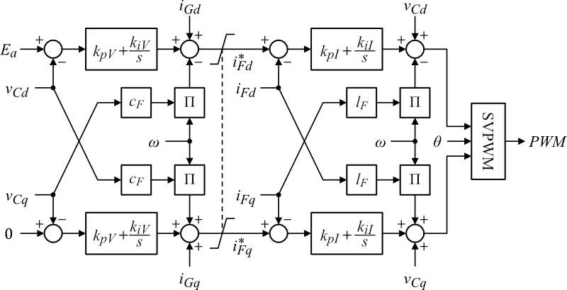
The controller was implemented using PI regulators in the synchronous reference frame with inner current and outer voltage control loops and space vector pulse-width modulation to operate the inverter. The following block diagram illustrates the inverter's control scheme.
The control algorithm for the inverter was programmed in C using a real-time operating system and was deployed on a FRDM-k64 development board equipped with a 32-bit ARM Cortex-M4 microcontroller. The microcontroller was further programmed to log and report all the control variables to allow for the real-time monitoring of the control loops.
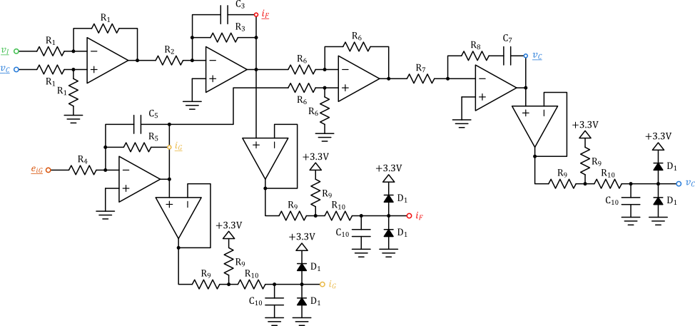
To develop and test the control scheme for the inverter I designed a custom analog simulation circuit to emulate the behavior of the inverter feeding a load through an LC filter. This testing platform I put togehter using inexpensive electronic components was the solution I came up with to carry out this project at home, as amidst the pandemic I had no access to the laboratory.
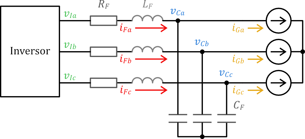
The following two figures show the circuit emulated by the analog simulation circuit and a schematic diagram of the simulation circuit itself, corresponding to a single phase of the emulated circuit. Two such analog circuits were used to emulate the behavior of two phases of the inverter and the third phase was simulated through software assuming the load was balanced.
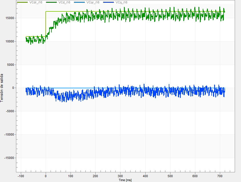
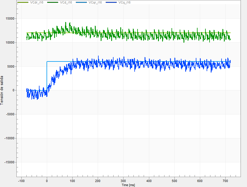
The tests carried out showed the microcontroller was able to swiftly control the inverter's current and voltage in the synchronous reference frame to follow the reference vector and adapt quickly to changes in the load. Furthermore, the control scheme proved itself resilient to measurement noise and capable of operating satisfactorily with fixed-point arithmetic and 16-bit variables.
The following images show the controller adjusting to step changes in the voltage reference vector in both the d and q axes of the synchronous reference frame. In both cases, the controller adjusts the voltage of the inverter to the new reference in less than 200 milliseconds with negligible between the two axes.
The following video illustrates the operation of the voltage and current controller and further information about this project can be found in the form of an infographic here or a technical report here.
For this project I developed and deployed a basic Virtual Synchronous Generator (VSG) control algorithm on an ARM microcontroller and tested it in a small power grid by means of harwdare-in-the-loop (HIL) simulation.
The control algorithm was programmed in C and deployed on a FRDM-k64 development board equipped with a 32-bit ARM Cortex-M4 microcontroller. This algorithm comprised the high level control of a Virtual Sychronous Generator of the Synchronverter type, which regulates the active and reactive power delivered to the grid by adjusting the virtual generator's frequency and voltage.
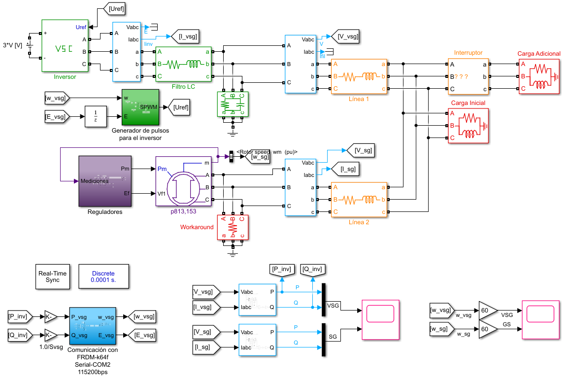
In order to test the control algorithm I developed in Simulink a model of a small power grid comprising a conventional thermal generating unit and a VSG feeding a load that would suddenly increase, causing the grid's frequency to drop. Using this model I carried out a HIL simulation where the microcontroller controlled the VSG's inverter through serial communication.
In this project the goal of the VSG was to enhance the grid's strength and resilience by means of inertia emulation and fast frequency response using battery energy storage and a grid-forming control strategy. To achieve this goal the VSG must react in the simulation to the sudden change in load injecting active power to slow down the frequency drop and allow the slower acting thermal generating unit to adjust its output according to its droop scheme.
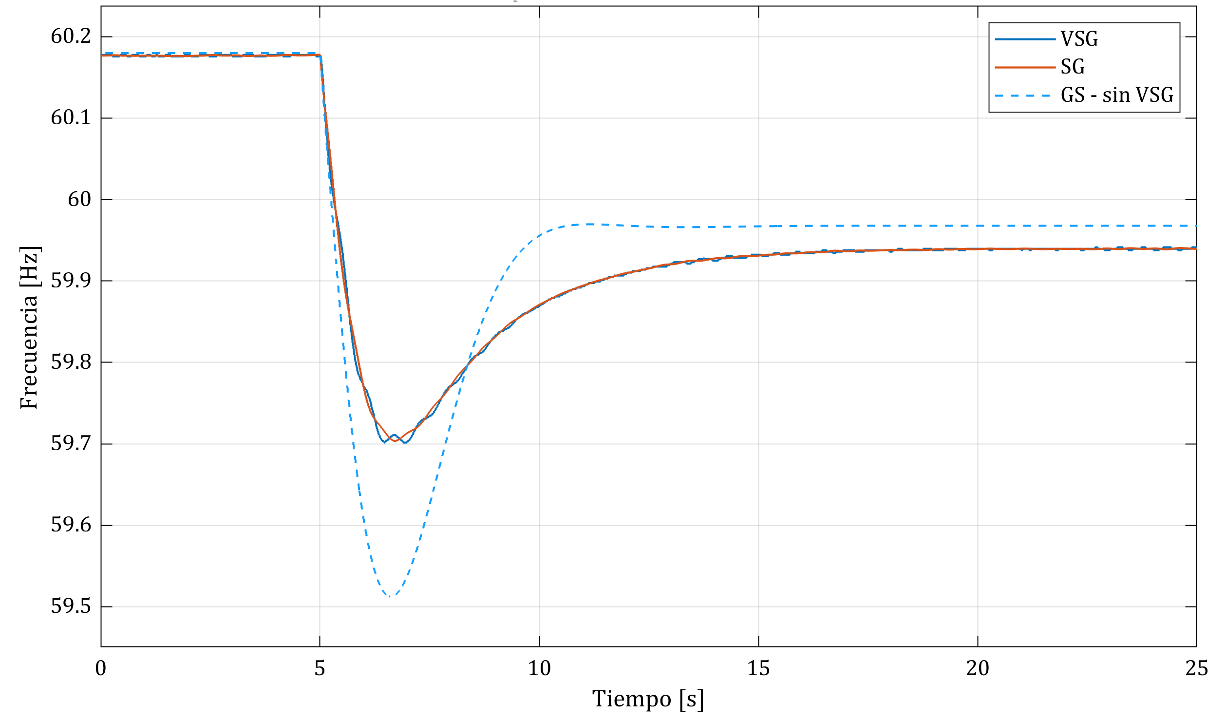
In the experiments carried out, the VSG performed successfully and it showed capable of reducing the rate of change of frequency and limiting the frequency drop in the power grid. Furthermore, the simulation showed the VSG was also capable of regulating its active and reactive power output according to an external reference adjusted by the user through a set of potentiometers connected to the microcontroller.
The following video illustrates the results of the HIL simulation and a further report on the results for this project may be consulted here.
luisdaniel11796@gmail.com